
Type 2 hardware provides new cables and connectors between the I/O cards and main boards in Cores and I/O Frames. Due to this change, the Type 2 hardware is not physically compatible with the older hardware. You can still integrate the new I/O Frames and Cores in the same system with older hardware, but the I/O cards are not interchangeable. Type 2 hardware can be identified by a yellow label on the back of the Core and I/O Frame, and the bottom of the I/O cards.
NOTE: This topic is for reference only. Refer to the Q-SYS Core and I/O Frame User Manual or the Type 2 Q‑SYS Core and I/O Frame User Manual for installation instructions.
The Core is Q-SYS' central processing unit. The Core processes and routes all audio, controls peripheral devices, manages firmware updates to the peripheral devices, all via a 1-gigabit Ethernet network. The Core has one slot available to add one of the I/O cards listed under Audio I/O cards.
The Q-SYS Core processing is accomplished using Intel® Xeon microprocessors and Intel server motherboards running, QSC-developed DSP algorithms under a customized Linux operating system. In addition, Sharc DSP is employed for some ancillary chores in peripheral devices.
NOTE: When a Core is shipped, the I/O card that is installed in the Core at shipping, is noted on the shipping label.
QSC currently has the Cores listed in the table below. The available storage capability for audio files and design files depends on the Multi-Track Player option purchased with the Core.
Due to hardware availability, the actual capacity may change.
VIDEO TUTORIAL: Video training presentation available online for Audio Tracks.
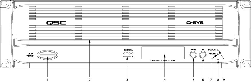
IMPORTANT: If you upgrade your hard drive, you will lose any files you had on the flash drive. Back up the files prior to upgrading.
Refer to Networked Audio Design for Core capacity information.
VIDEO TUTORIAL: Video presentation available online for Identify Device Button.
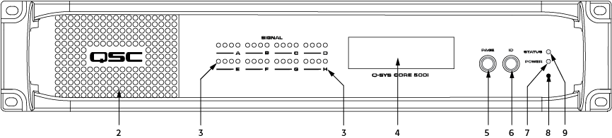
For Cores 1000, 3000, 4000, 250i, and 500i: Insert a standard paperclip or other suitable tool into the pinhole and hold for 10 seconds to reset all network settings to their factory defaults.
For Cores 1100, 3100: Insert a standard paperclip or other suitable tool into the pinhole and hold for 3 seconds, the message "Press ID to reset, any other button to cancel" displays. Press ID to set all network settings to their factory defaults.
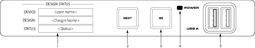
For Core 110f: Press and hold the Next and ID buttons for 3 seconds the message "Press ID to reset, any other button to cancel" displays. Press ID to set all network settings to their factory defaults.
VIDEO TUTORIAL: For a comparison of the Front and Back Panel with an I/O Frame, watch the video presentation of the Core and I/O Frame.
The following connections use the black Euro plug.
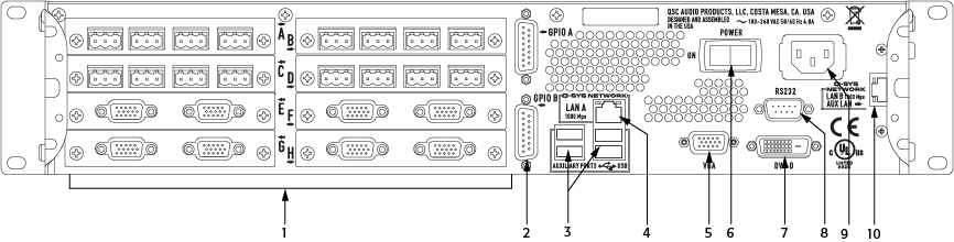
The Core 250i Type 2 allows eight of the following Type 2 I/O cards or a card/cover. Each I/O card supports four channels. The cards are not hot-swapable, and must be replaced by a qualified technician.
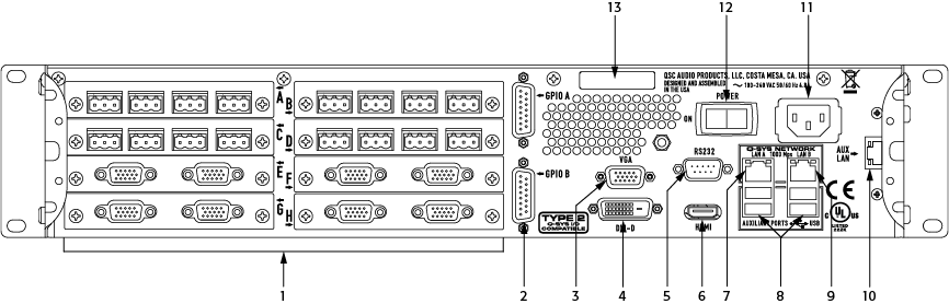
The Core 500i Type 2 allows eight of the following Type 2 I/O cards or a card/cover. Each I/O card supports four channels. The cards are not hot-swapable, and must be replaced by a qualified technician.
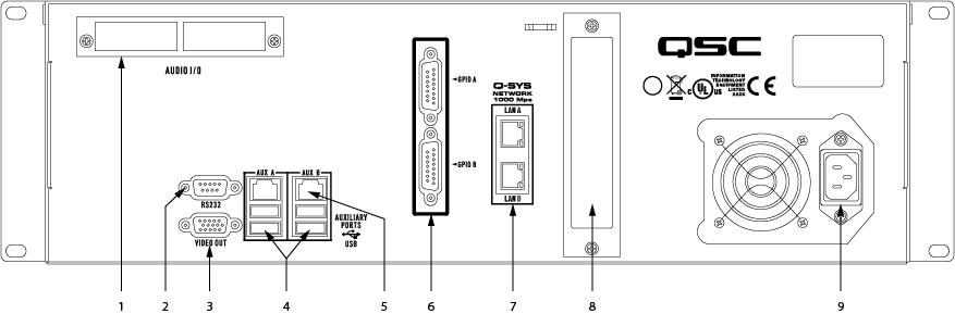
The Core Type 2 allows one of the following Type 2 I/O cards or a card/cover. The cards are not hot-swapable, and must be replaced by a qualified technician.
|
System Hardware |
|
|
|||||||||||||||
|---|---|---|---|---|---|---|---|---|---|---|---|---|---|---|---|---|---|
|
Description |
System processor and control engine |
||||||||||||||||
|
Capacity |
|||||||||||||||||
|
Network Audio Channels |
|||||||||||||||||
|
|
|
|||||||||||||||
|
End Node Capacity |
|
|
|||||||||||||||
|
Processing (Channels of 32-bit audio) |
|
|
|||||||||||||||
|
I/O Capacity |
Up to 32 channels. Requires purchase of I/O cards | ||||||||||||||||
|
Line Voltage Requirements |
100 VAC - 240 VAC, 50 - 60 Hz |
||||||||||||||||
|
Dimensions (HWD) |
5.25" x 19" x 15" (133.35 mm x 482.6 mm x 381 mm) |
3.5" x 19" x 15" (88.9 mm x 482.6 mm x 381 mm) |
|||||||||||||||
|
Accessories Included |
6 ft UL/CSA/IEC line cord User Manual QSC Warranty Optional audio I/O ship kit |
||||||||||||||||
1. At least 128, and up to 512 network audio channels when sending 8 or more channels per network audio stream.2. Using maximum fan-out with 16-channel unidirectional I/O Frames.3. The CAES4 card (AES3 input/output) doubles the audio channel count of any slot in which it is used. |
|||||||||||||||||
|
System Hardware |
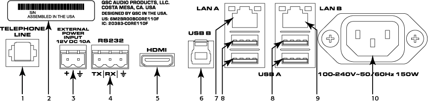
Core 110f |
|---|---|
|
Description |
System processor and control engine and I/O unit |
|
Input Frequency Response 20 Hz to 20 kHz @ +21 dBu |
+0.05 dB/-0.5 dB |
|
Input THD+N @ 1 kHz |
@ +21 dBu Sensitivity and @ +21 dBu input < 0.1% @ +21 dBu Sensitivity and @ +10 dBu input < 0.0015% @ +10 dBu Sensitivity and @ +8 dBu input < 0.001% @ -10 dBu Sensitivity and @ -10.5 dBu input < 0.001% @ -39 dBu Sensitivity and @ -39.5 dBu input < 0.007% |
| Input to Input Crosstalk @1 kHz |
@ +21 dBu sensitivity 110 dB Typical, 90 dB Max @ +10 dBu sensitivity 105 dB Typical, 90 dB Max @ -10 dBu sensitivity 100 dB Typical, 90 dB Max @ -39 dBu sensitivity 75 dB Typical |
| Input Dynamic Range |
@ +21 dBu Sensitivity > 109.5 dB @ +10 dBu Sensitivity > 106.4 dB @ -10 dBu Sensitivity > 104.6 dB |
|
Input Common Mode Noise Rejection |
|
|
@ +21 dBu Sensitivity |
< 51, 20 Hz – 3 kHz < 43, 20 Hz – 10 kHz < 36, 20 Hz – 20 kHz |
|
@ +10 dBu Sensitivity |
< 57, 20 Hz – 3 kHz < 47, 20 Hz – 10 kHz < 41, 20 Hz – 20 kHz |
|
@ -10 dBu Sensitivity |
< 67, 20 Hz – 3 kHz < 58, 20 Hz – 10 kHz < 53, 20 Hz - 20 kHz |
|
@ -39 dBu Sensitivity |
< 60, 20 Hz – 3 kHz < 54, 20 Hz – 10 kHz < 50, 20 Hz – 20 kHz |
|
Input Impedance (balanced) |
7.2k Ω Nominal |
|
Input Sensitivity Range (1 dB Steps) |
-39 dBu min to +21 dBu max |
|
Output Frequency Response 20 Hz to 20 kHz @ all settings |
+0.2/-0.5 dB |
|
Output THD |
0.005% Typical, +21 dBu Max Output Level |
|
EIN (no weighting, 20 Hz to 20 kHz) |
< -121 dB |
|
Output Crosstalk @ 1 kHz |
> 100 dB Typical, 90 dB max |
|
Output Dynamic Range |
> 108 dB |
|
Output Impedance (balanced) |
332 Ω |
|
Output Level Range (1 dB Steps) |
-39 dBu min to +21 dBu max |
|
Capacity |
|
|
Q-LAN Channels |
128 |
|
AEC Channels |
16 |
|
Core-to-Core Streaming Channels |
128 |
|
MTP |
Default = 16, With optional MD-110 SSD and MTP-32 = 32 |
| USB B (Audio) | |
|
Bit Depth |
Selectable 16-bit, 24-bit |
|
Number of Channels |
up to 16 x 16 |
|
Sample Rate |
48 kHz |
|
Phantom Power |
+48 VDC, 10 mA per input max |
|
Sampling Rate |
48 kHz |
|
Power Consumption |
60 watts, typical. 120 watts max |
|
A/D – D/A Converters |
24-bit |
|
BTU / Heat load |
205 BTU/Hour |
|
Line Voltage Requirements |
100 VAC - 240 VAC, 50 - 60 Hz |
|
Unit Dimensions (HWD) |
1.75" (44 mm) x 19.0" (483 mm) x 11.2" (283 mm) |
| Shipping Dimensions (HWD) |
6" (152 mm) x 23" (584 mm) x 14" (356 mm) |
|
Unit Weight |
10.8 lbs (4.9kg) |
|
Shipping Weight |
11.5 lbs (5.2 kg) |
|
Accessories Included |
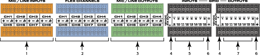
Core 110f Unit 6 ft UL/CSA/IEC AC power cord Phone cord Euro-style connectors, color coded 3-pin Mic/Line In (orange) (8) 3-pin Flex Channel (blue) (8) 3-pin Line Outputs (green) (8) 10-pin GPIO (black) (4) 2-pin Euro-style connector for +12 VDC 10 A (1) 3-pin Euro-style connector for RS232 TX / RX (1) Rubber Feet (4) QSC Warranty Core 110f Installation Guide |
© 2009 - 2016 QSC, LLC. All rights reserved. QSC and the QSC logo are trademarks of QSC, LLC in the U.S. Patent and Trademark office and other countries. All other trademarks are the property of their respective owners.
http://patents.qsc.com.
![]()
 Related Topics